LED Chaser Circuit using Transistors Circuit Diagram 74HC595 8-Bit Shift Register Pinout . The 74HC595 is an 8-bit serial-in, parallel-out shift register IC that is commonly used to drive leds motor or any other electronic equipment.. PIN(Q0 - Q7) Output pin of the IC, that can be controlled serially. GND Connected to the Ground of the Circuit.. MR Master Reset: Resets all outputs as low. Must be held high for normal operation

Circuit Diagram with 200 LED Chaser Circuit. The basic reverse forward LED circuit using single LEDs can be studied elaborately in this LED scanner article, and the video can be witnessed below: How to Connect the LEDs. The following diagram illustrates the connection arrangement of the LEDs to the above circuit. [NEW] LED Chaser Circuit Using 8 Bit Shift Register and 555 Timer IC | 555 Timer Projects | BC547In this video we are going to make a new LED chaser Circuit
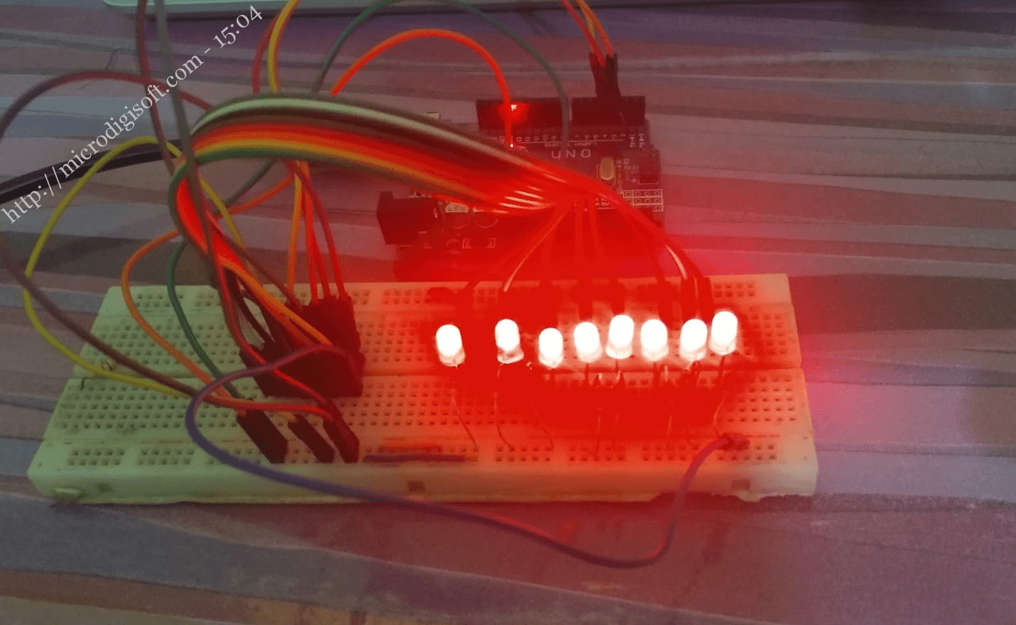
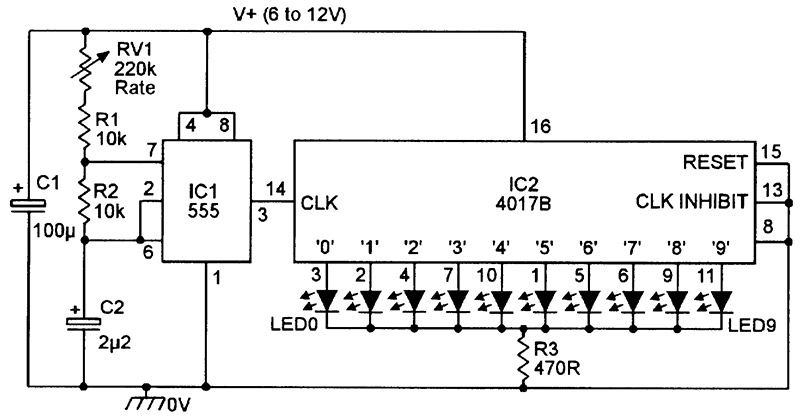
[NEW] LED Chaser Circuit Using 8 Bit Shift Register and 555 Timer IC ... Circuit Diagram
The shift register then shifts the pulses to its output pins in a specific pattern, which can be programmed using the microcontroller. In addition to reducing the number of output pins required from the microcontroller, shift registers also provide flexibility in the LED chaser circuit design. The pattern of the LED lighting sequence can be
A shift register is an electronic component that allows the user to control multiple outputs using a single input signal. Shift registers are commonly use in LED chaser circuits to control the pattern of LED lighting sequences. A Shift Register is basically a Serial-to-Parallel Converter IC.

10 Simple LED Chaser Circuit Diagrams Explained [Knight Rider, Scanner ...
how to Control 16 LEDs with 74HC595 Shift Register | 16 Channel led light Chaser using 74HC595Code, Schematics and Proteus Simulation Download link:- https:/
